

Structural Features
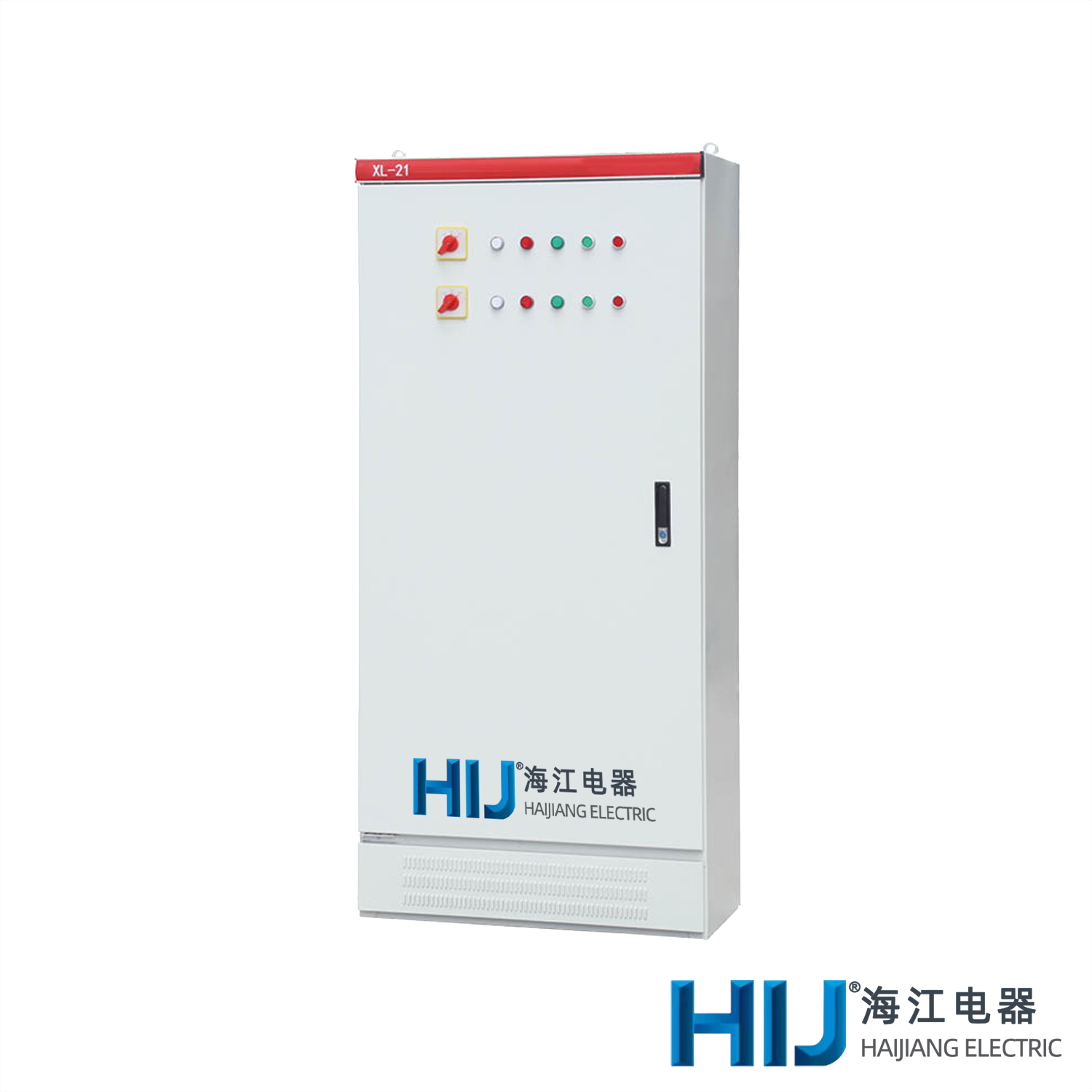
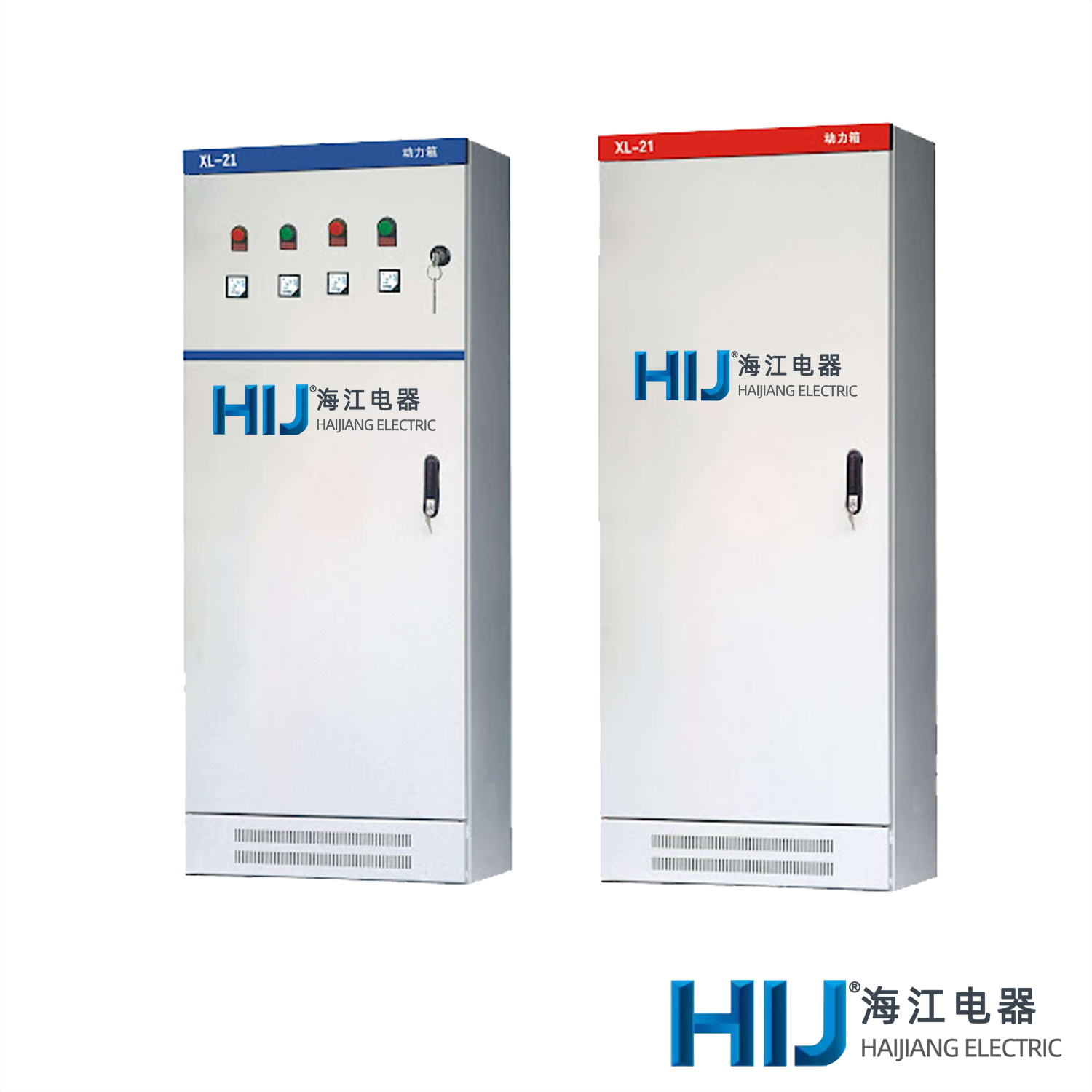
● This device is designed for floor installation and can be directly installed under the transformer. The cabinet is constructed from high-quality steel plates, welded or assembled. The operating handle of the knife switch is installed on the right column of the cabinet, serving as a power cut-off and switching mechanism.
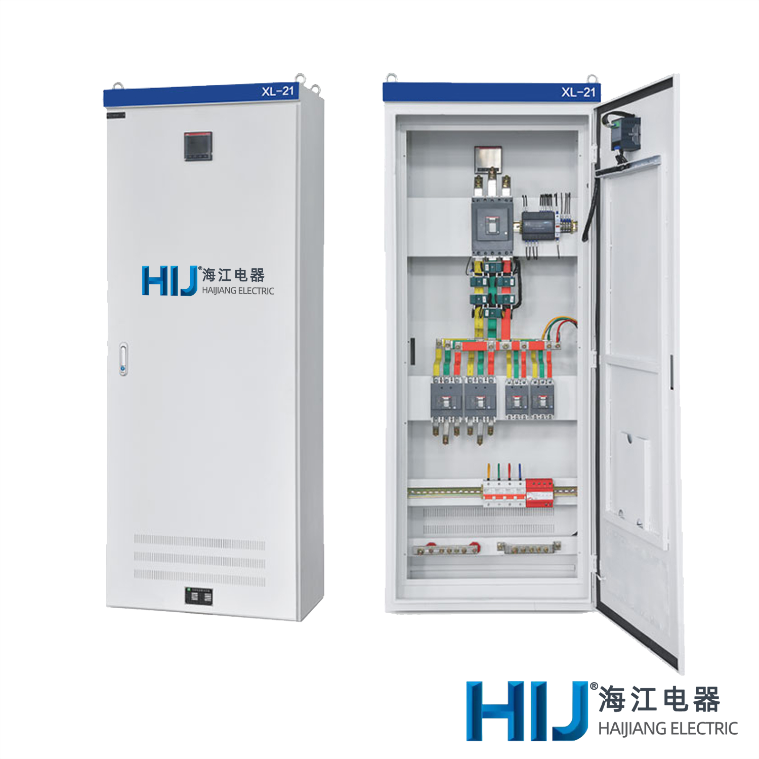
● A voltmeter is installed on the front of the power distribution box to indicate the voltage of the busbar. The front of the power distribution box is equipped with a door, which, when opened, exposes all equipment inside for easy maintenance.
● The power distribution box utilizes newly designed components domestically developed, featuring compact structure, convenient maintenance, and flexible circuit arrangement.
● Circuit breakers are incorporated into the power distribution box for short-circuit protection, and operation buttons can be installed in front of the door.
● Operation Mode: Manual
● Installation Method: Vertical Installation
● Wiring Method: Fixed Wiring
Operating Environment Requirements
● The altitude should not exceed 4000 meters.
● The ambient temperature or surrounding air temperature should not exceed +40°C, with an average temperature not exceeding +35°C within a 24-hour cycle. The surrounding air temperature should not drop below -10°C.
● The air should not contain an excessive amount of dust, acid, salt, corrosive, or explosive gases.
● The relative humidity should not exceed 50% at the highest temperature of +40°C. However, at lower temperatures, higher relative humidity is permitted, such as 90% below +20°C, but occasional condensation due to temperature changes should be considered.
● Special requirements from the user can be addressed through consultation with our company.
● Cabinet
|
Model |
Rated Current(A) |
Rated Current of the Fuse(A) |
Note |
|
HR3-400/34 |
400 |
150/200/250/300/350/400 |
When using isolation knife switch, there is no fuse. |
● Air Circuit Breaker
|
Model |
Rated Current(A) |
Rated Current of the Disconnector(A) |
Breaking Capacity(kA) |
|
C65 |
65 |
1/2/4/6/10/16/20/25/32/40/50/63 |
6/10 |
|
CM1-100/330 |
100 |
15/20/25/30/40/50/60/80/100 |
35/50/65 |
|
CM1-225/300 |
225 |
100/120/140/170/200/225 |
35/50/65 |
|
CM1-630/330 |
630 |
400/450/500/550/630 |
35/50/65 |
● Current Transformer
|
Model |
Primary Current(A) |
Secondary Current(A) |
|
LMK-0.66 BH-0.66 |
75/100/150/200/300/600 |
5 |
● Fuse
|
Model |
Rated Current(A) |
Rated Current of the Fuse(A) |
|
NT00C-15 |
15 |
2/4/5/6/10/50 |
|
NT00C-60 |
60 |
20/25/30/35/40/50/60 |
|
NT00C-100 |
100 |
30/40/50/60/80/100 |
|
NT00C-200 |
200 |
80/100/120/150/200 |
|
NT00C-400 |
400 |
150/200/250/300/350/400 |

 +86-0577-62885555
 contact@cnhij.com
 Zhangwan Industrial Zone, Baixiang, Yueqing, Wenzhou, Zhejiang Province, China
 Company Profile
 Certificate
 Manufacturing


 Download
 FAQ
FAQ Corporate News
 Contact Information
 Online Message