
Structural Features
● Increase the heat capacity of the transfer component to significantly reduce the additional temperature rise caused by the transfer component for connectors, cable heads, and spacer plates.
● Ensure clear and reliable separation between functional units and compartments, preventing the malfunction of one unit from affecting the operation of others and limiting faults to a minimum range.
● The horizontal arrangement of busbars provides good dynamic and thermal stability, capable of withstanding the impact of a short-circuit current of 80/176kA.
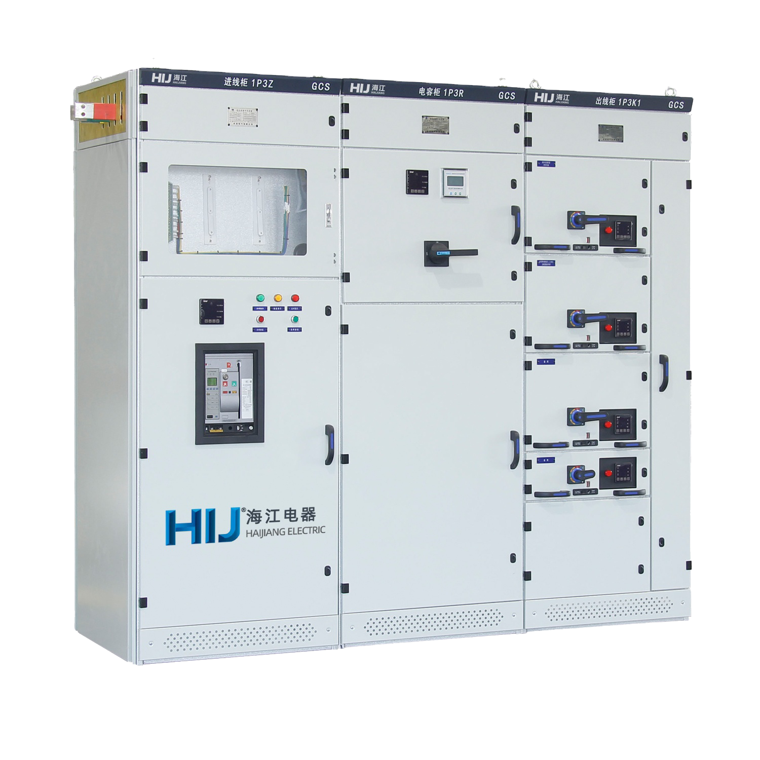
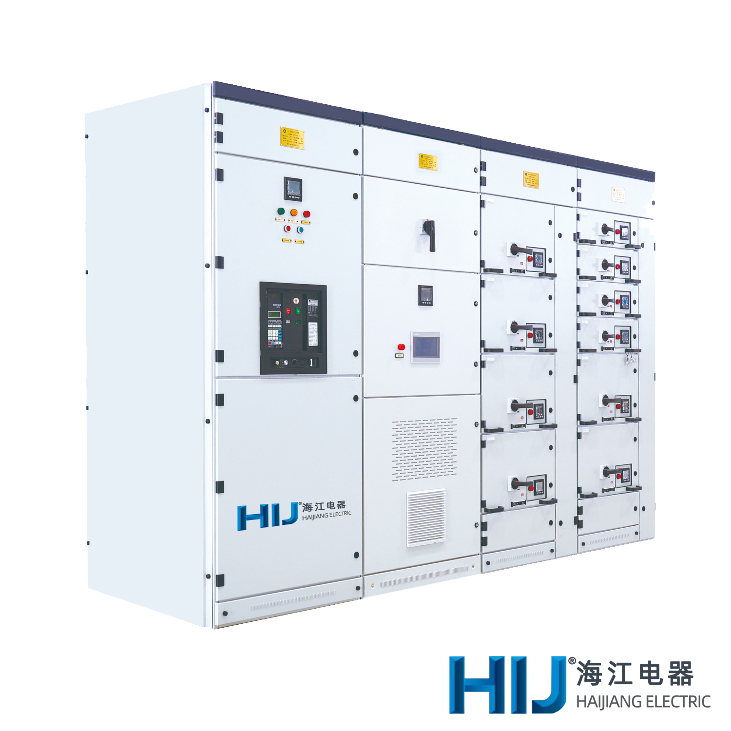
● MCC cabinets are designed with up to 22 circuits per cabinet, considering the needs of large-capacity power generation and automation in industries such as petrochemical systems.
● Device-to-external cable connections are completed in the cable compartment, allowing cables to enter and exit from the top and bottom. Current transformers are installed in the cable compartment for convenient installation and maintenance.
● Within the power distribution systems, limiting reactors can be used to match and restrict short-circuit currents, stabilize busbar voltage at a certain value, and partially reduce the short-circuit strength requirements for components.
● Drawer units are equipped with a sufficient number of secondary connectors (32 pairs for 1 unit and above, 20 pairs for 1/2 unit), meeting the requirements for the number of connection points for computer interfaces and self-control circuits.
Operating Environment Requirements
● Ambient air temperature: -5°C to +40°C; the daily average temperature should not exceed +35°C. If it exceeds this range, the capacity should be derated according to the actual situation.
● Altitude: 2000m and below.
● The air should be clean, with relative humidity not exceeding 50% at the highest temperature of +40°C. Higher relative humidity is allowed at lower temperatures, for example, 90% at +20°C, but considering temperature changes, occasional condensation may occur.
● The installation inclination should not exceed 5°, and the entire cabinet row should be relatively flat (in accordance with GBJ232-82 standards).
● Switchgear should be installed in places without severe vibration and impact, and where electrical components are not subjected to corrosion.
● Note: When you have special requirements, please feel free to negotiate solutions with us.
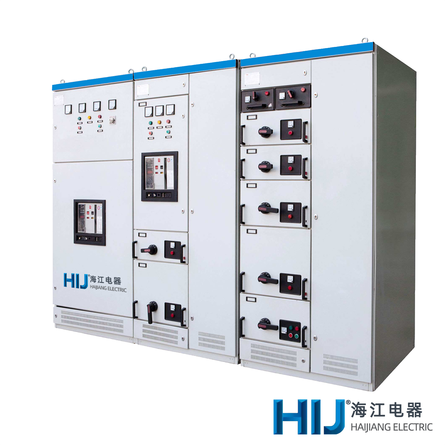
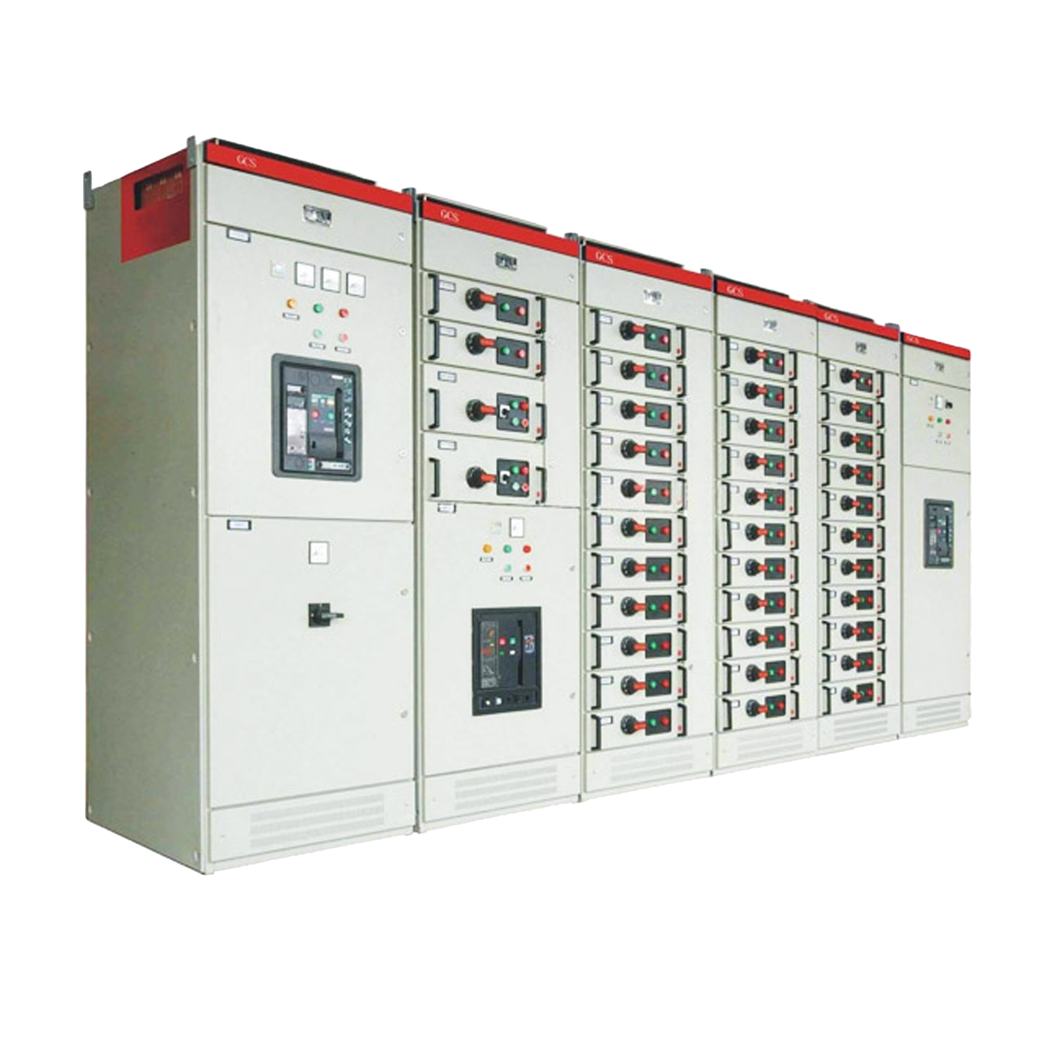
Structure Overview
● The main frame adopts the 8ME open-section steel, with mounting holes on both sides with module sizes of 20mm, 100mm, and Φ9.2mm, allowing for flexible and convenient internal installation.
● The main frame assembly is designed in two forms: fully assembled structure and partially welded structure (side frame and beam), providing options for users.
● Various functional compartments of the device are isolated from each other, divided into functional unit compartments, busbar compartments, and cable compartments. The functions of each compartment are relatively independent.
● Horizontal busbars adopt a cabinet-back horizontal arrangement to enhance the busbar's ability to resist electromagnetic forces, providing the basic measures for the main circuit of the device to have high short-circuit strength.
● The design of the cable compartment facilitates easy entry and exit of cables from top to bottom.
● The device uses a universal cabinet size series (see the table below):
|
Parameters Name |
Unit |
Content |
|
|
Rated Voltage for Main Circuit |
V |
AC:380/400/600 |
|
|
Rated Voltage for Auxiliary Circuit |
V |
AC:220/380/400 DC:110/220 |
|
|
Rated Frequency |
HZ |
50/60 |
|
|
Rated Insulation Voltage |
V |
600/1000 |
|
|
Rated Current |
Horizontal Busbar |
A |
4000 |
|
Vertical Busbar |
A |
1000 |
|
|
Rated Short-Time Withstand Current of Busbar |
kA/1s |
50/80 |
|
|
Rated Peak Withstand Current of Busbar |
kA/0.1s |
105/176 |
|
|
Power Frequency Test Voltage |
Main Circuit |
V/min |
2500 |
|
Auxiliary Circuit |
V/min |
1760 |
|
|
Busbar |
Three-phase & Four-wire |
/ |
A, B, C, PEN |
|
Three-phase & Five-wire |
/ |
A, B, C, P, EN |
|
|
Protection Level |
/ |
IP30/IP40 |
|
|
Height (mm) |
220 |
|||||||||
|
Width (mm) |
400 |
600 |
800 |
1000 |
||||||
|
Depth (mm) |
800 |
1000 |
800 |
1000 |
600 |
800 |
1000 |
600 |
800 |
1000 |

 +86-0577-62885555
 contact@cnhij.com
 Zhangwan Industrial Zone, Baixiang, Yueqing, Wenzhou, Zhejiang Province, China
 Company Profile
 Certificate
 Manufacturing


 Download
 FAQ
FAQ Corporate News
 Contact Information
 Online Message